Core R Theta — Part 1
Building and configuring a four-axis Core R Theta printer, from Duet controller integration to nonplanar slicing and toolpath testing.
Introduction
In the fall of 2025, I met John Cheng and Joseph Opera through the University of North Georgia’s Engineering Student Guild. Both are mechanical-engineering students developing a 4-axis 3D printer known as the Core R Theta—an experimental system that introduces an additional rotational axis to increase print efficiency and structural durability.
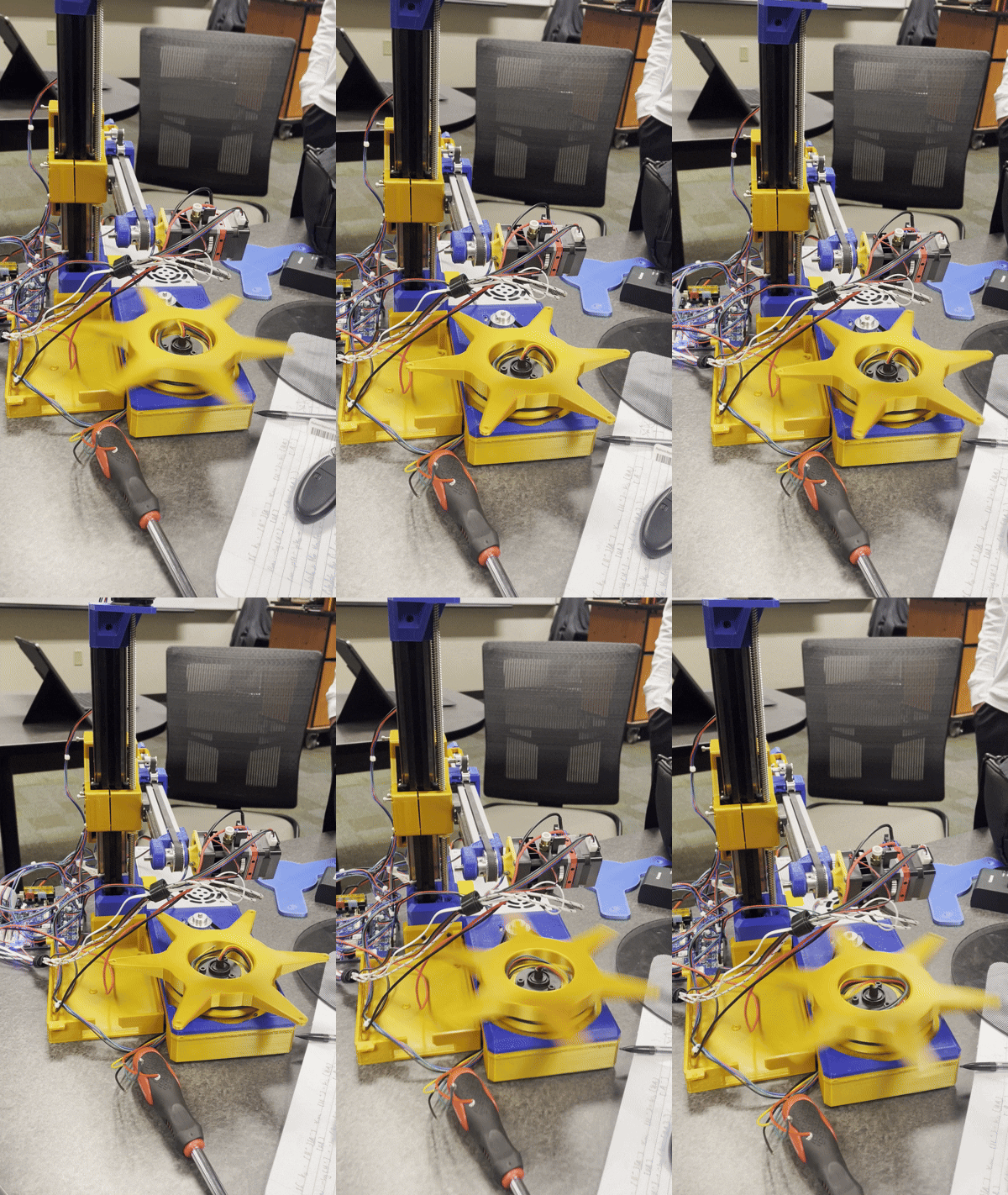
Originally designed by Joshua Bird, a student from Cambridge, the printer is fully open-sourced. At the time, only three other research groups in the world were working on the concept, so UNG commissioned John and Joseph to replicate and extend Bird’s design under the direction of Dr. Forringer. Here’s Bird’s working prototype.
What’s most remarkable about the Core R Theta is the human-like motion with which it prints. Two NEMA-17 stepper motors drive the X-axis. Depending on whether they rotate together or independently, they can either translate the extruder linearly or rotate its orientation. This allows the printer to reach angles impossible for conventional Cartesian or Delta systems—reducing the need for supports and producing parts that are stronger along their stress lines.
Design
By the time I joined, John and Joseph had already completed most of the assembly and mechanical optimization. Here’s the Fusion 360 model: 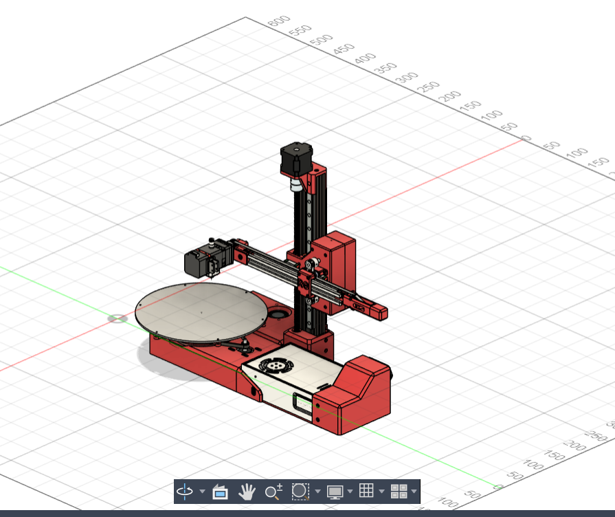
They re-engineered the Z-axis and modified the extruder mount for greater stability. The most significant change for me, however, was their choice to switch to a completely different controller board—something that would define my role in the project.
My favorite mechanical detail was the dual-motor belt system on the X-arm: 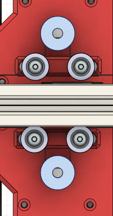
Each motor drives one side of the belt. When they move synchronously, the extruder translates; when they move independently, the extruder rotates. It’s an elegant and compact way to achieve orientation control.
Motherboard Integration
This is where I entered the picture. The original Core R Theta was designed for a Fly E3 Pro V3, but the UNG team opted for a Duet 3 Mini 5+ instead. Both run RepRap Firmware and use TMC2209 stepper drivers, yet their pinouts differ significantly.
That meant manually translating every signal path from one board to the other—a process that involved poring over schematics, verifying continuity, and updating configuration files line by line. 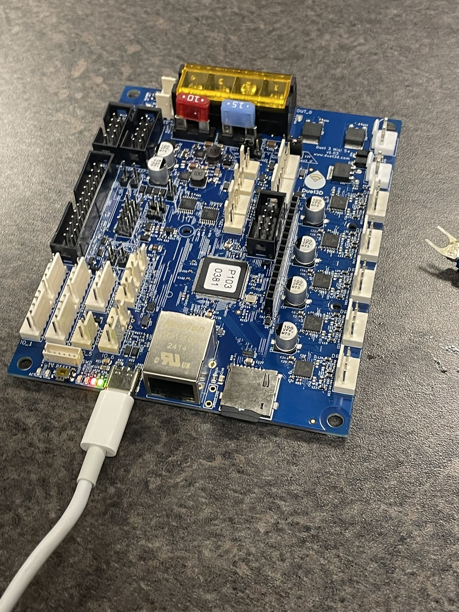
For example, the Z-probe input that originally mapped to the X-STOP (pin 25) on the Fly E3 corresponds to io1.in under the IO_1 header on the Duet 3 Mini. 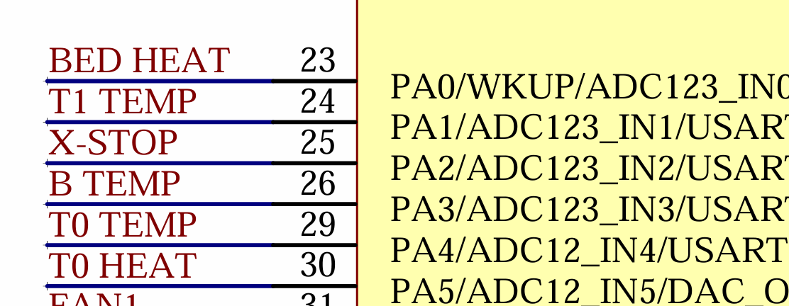
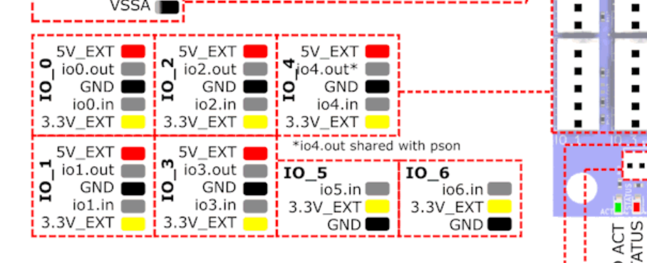
In RepRap Firmware, this translation is defined through G-code. The following command configures the probe type, input pin, dive height, and travel speed:
M558 P5 C"^io1.in" H5 F2000:500 T6000 A1
P5 specifies a mechanical switch probe, while C"^io1.in" assigns the correct input pin with an active-high signal.
Here I’m soldering the probe wiring before final testing: 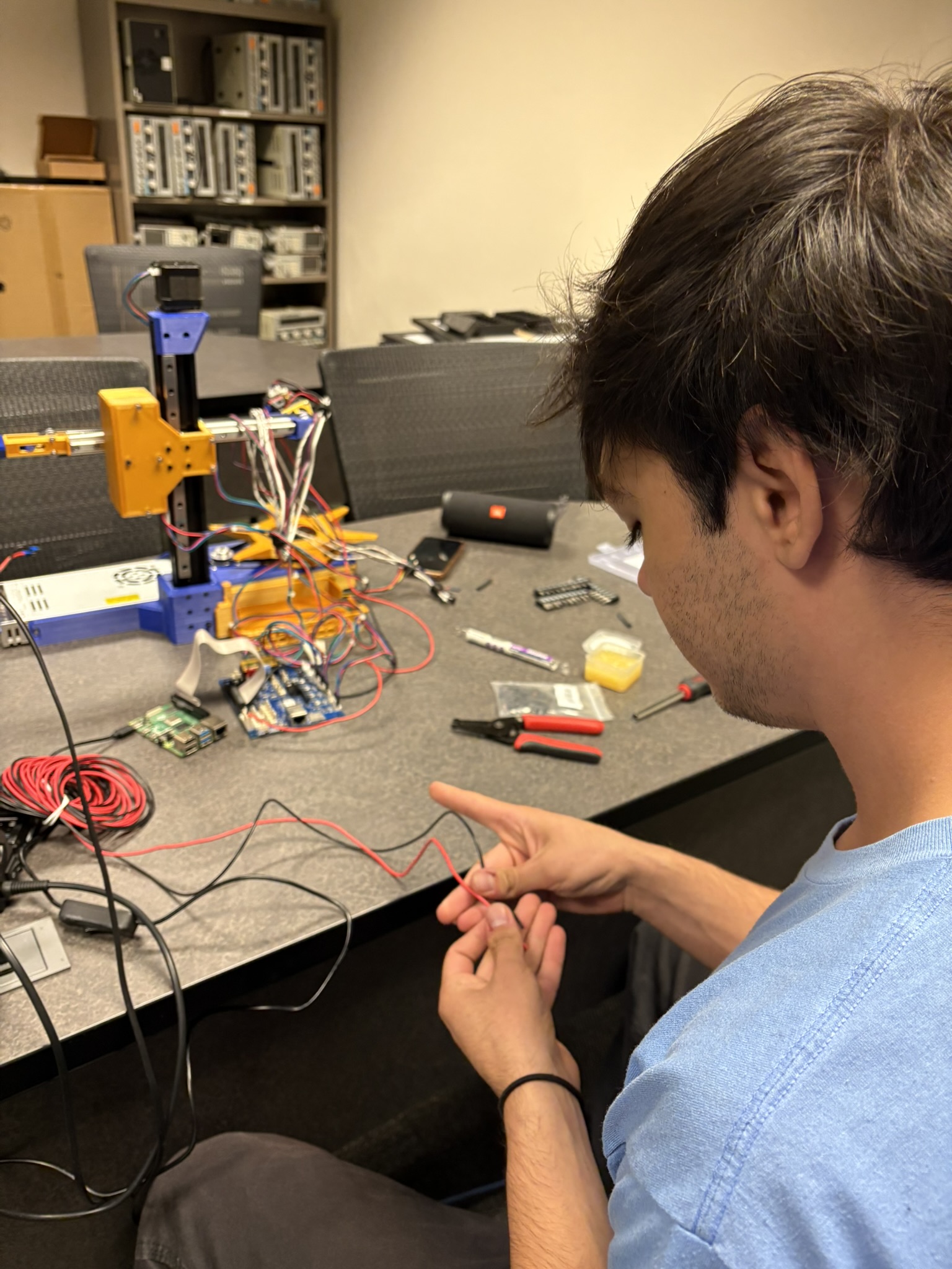
G-Code Configuration
G-code is the low-level language that controls automated tools in additive manufacturing. It maps stepper-motor drivers to their respective axes and handles every motion command.
For instance:
M569 P4 S1
This line sets the direction of the stepper driver connected to the Z-axis motor (S1 reverses its orientation).
Another key snippet comes from the Z-homing routine:
G91 G1 H2 Z10 F6000 ; lift Z relative to current position G90 G1 X0 Y0 ; move to center of bed G30 G91 G1 Z5 F6000 ; lift Z again G90
Here, G91 enables relative positioning, and G1 executes controlled linear moves at a specified feed rate (F). This script lifts the nozzle, centers the printhead, triggers the probe (G30), and retracts safely afterward.
The Duet3D G-code documentation was invaluable throughout the process.
S4_Slicer - Generic Non-Planar Slicer
Joshua Bird also developed a slicer for the Core R Theta. Slicing is pre-processing step where 3D models are converted into G-code. jyjblrd/S4_Slicer: Generic Non-Planar Slicer is his own implementation, with some unique features. Since the Core R Theta operates on an extra axis with additional degrees a freedom, the extruder can reach new angles. Instead of a layer by layer approach like traditional printers, new paths can be taken for the Core.
The slicer begins by converting an STL file into a tetrahedral volume mesh using tetgen, the builds cell neighbor graphs and a NetworkX weighted graph. The code can now reason out local rotations inside the volume and turn them into one continuous deformation of the whole part.
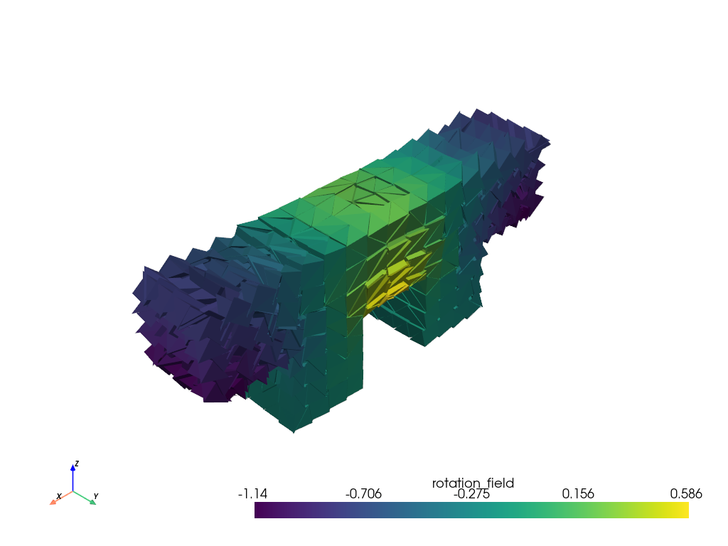
Each cell is then computed and the most downward face normal is found (essentially the normal with the most negative Z). Overhang angles are calculated and paths to bottom cells run multi-source Dijkstra.
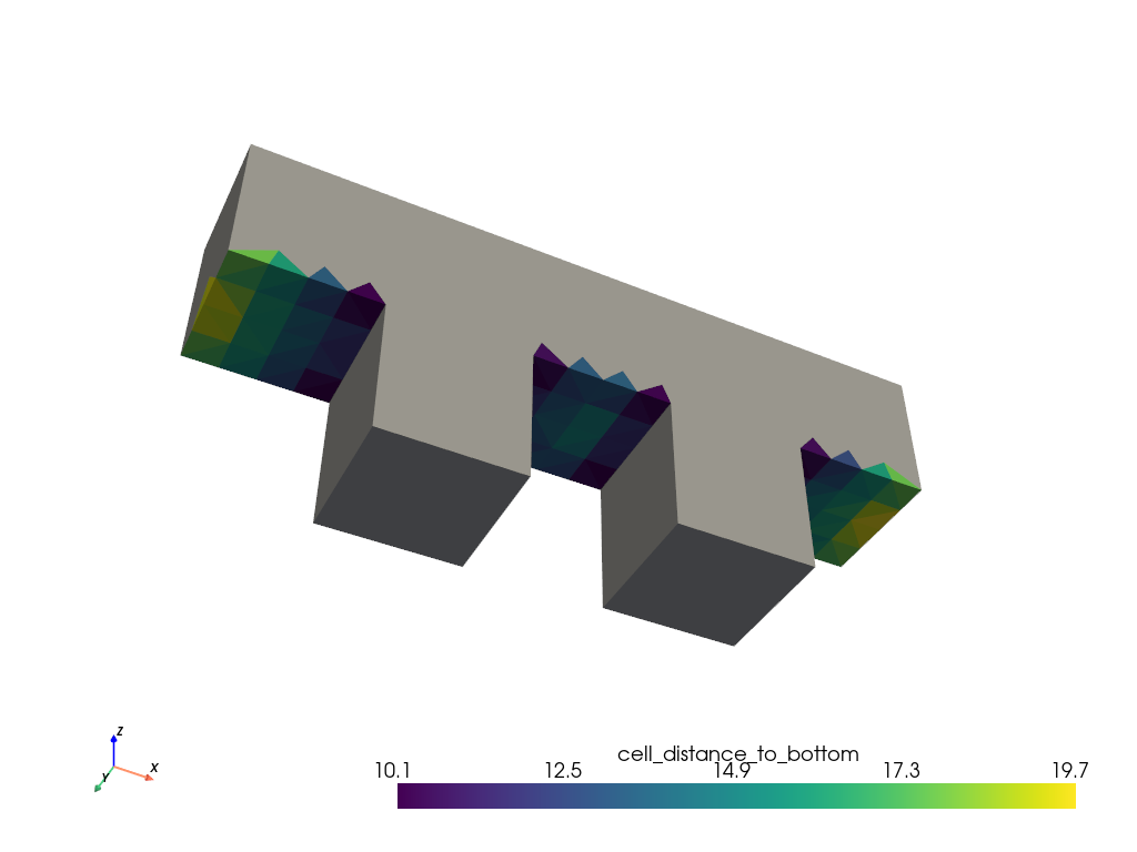
By calculating the bottom-most cells we can now defined how the part should be "rolled". This is visually represented with the bottom-most cells in color, with darker colors showing the greatest support in weight, with the least amount of roll necessary.
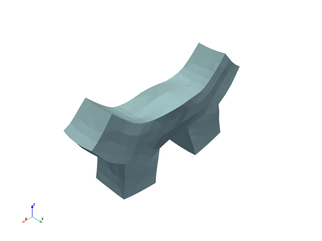
The mesh is deformed and ready for slicing. Then it is "re-formed", with the new toolpaths mapped.
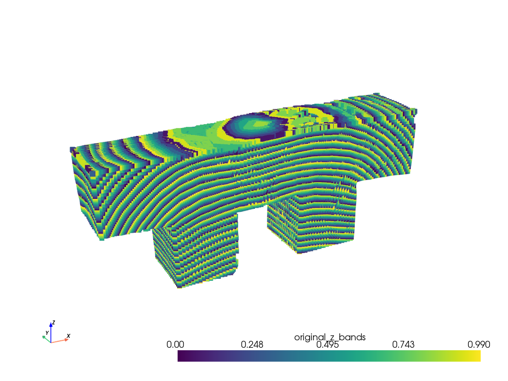
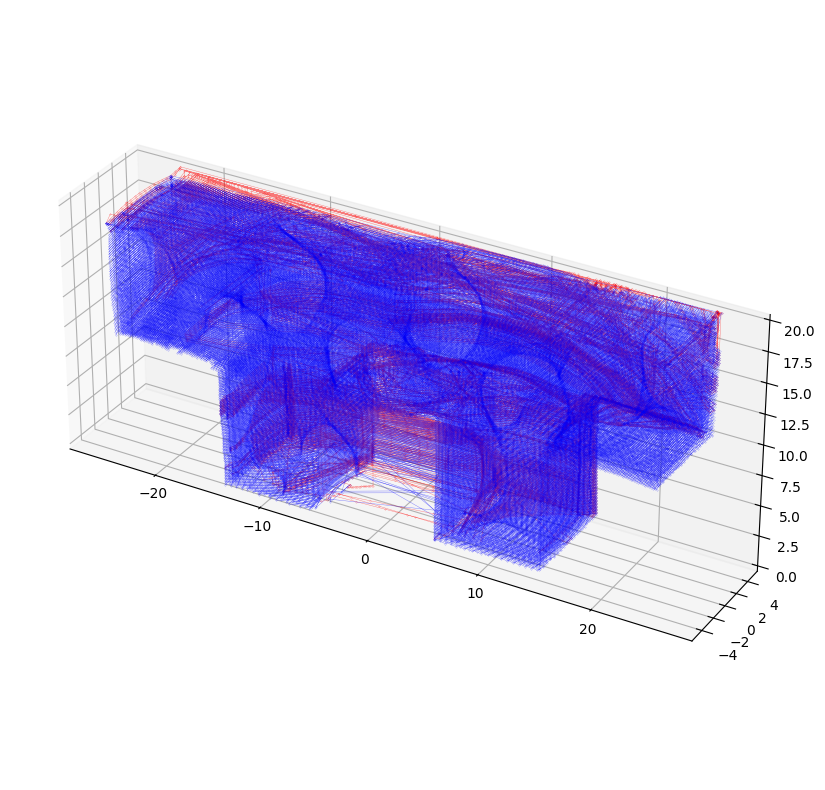
The slicer is an extensive research project in itself and something I'll be working on next semester, as well as fine-tuning the final system. The idea of deforming meshes to improve toolpath and remove supports is a new one, and definitely worth its own study.
The next step would be to finish wiring the extruder. The G-code does run however, the extruder outputs are just sending arbitrary voltage at this point. Below is the first G-code test run, theoretically printing out the model above.