Gauntlet HID — Part 1
Building a wearable ESP32 controller with an IMU, quaternion-based orientation tracking, and mouse-control firmware.
Intro
Diving deeper into electronics, I wanted a fun project to work on. One night, after a few hours of play Cyberpunk 2077, I had a dream where I was controlling some drones and robotics with my hands. I set out to make a human interface device (HID) to do just that. Some kind of universal controller fitted to a glove that, with the wave of my hand, I could control all matter of electronics. That's how I started Gauntlet.
First things first, I need some way to map hand movement into input. I learned about Inertial Measure Units (IMU) that combine accelerometers and gyroscopes to get orientation. Adafruit's MPU6050 seemed like a great choice, hooking into an ESP32 through I2C. 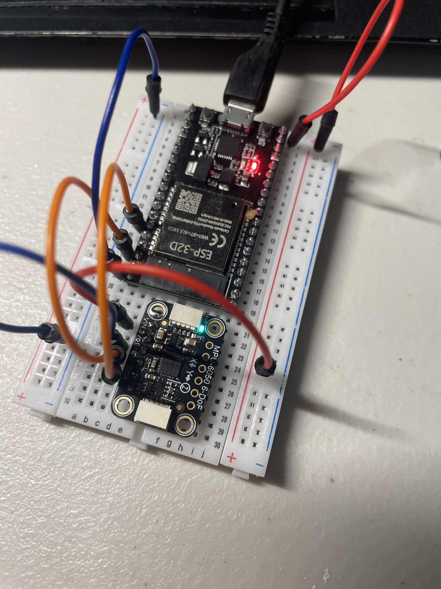
This was after burning out a few bootleg models off of Amazon, before finally settling with the real Adafruit chip. To get orientation was the next challenge, here comes the math.
Orientation Math
I was using Euler angles the whole time, which has its quirks.
Euler Angles
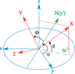 We can relate the orientation of a body to a fixed coordinate system using Euler angles. We can determine the orientation of the body by considering how much it has rolled to one side, pitched forwards or backwards, and yawed to the left or right. These are our three angles.
Yaw (ψ) – rotation about the Z-axis Rotates the object left or right.
Pitch (θ) – rotation about the new Y-axis (after yaw) Tilts the object forward or backward.
Roll (φ) – rotation about the new X-axis (after yaw and pitch) Rolls the object around its front-to-back axis.
It's intuitive and straightforward, but we're met with a serious issue: Gimbal Lock. When two rotational axes align, we lose a degree a freedom, since at this point we can't differentiate between the two rotations. For example, say pitch hits 90 degrees. At this point, yaw and roll become parallel.
Complex numbers in 2D
$$q = w + xi + yj + zk$$ Where $w$ is the real number, $x, y, z$ are imaginary, and $i, j, k$ are basis parts that satisfy the following: $$i^2 = j^2 = k^2 = ijk = -1$$ On a plane, let's assume $i$ means to rotate by 90 degrees. We move 3 steps to the right, rotate 90 degrees, then move 2 steps up, we end up with the coordinates $3 + 2i$, as opposed to the Cartesian coordinate $(3,2)$. Remember from the equation for the basis numbers in quaternions: $$i^2 = -1$$ So multiplying our coordinate by $i$ should give us a 90 degree rotation counterclockwise. $$i(3+2i) = 3i + 2i^2 = -2 + 3i$$ Are it's Cartesian equivalent to $(-2, 3)$. Now we're getting an idea of rotating using complex numbers about the plane. I'm not going to pretend to understand anything about complex numbers on the plane. We can rotate another 90 degrees, and if we view an origin vector for our coordinates, we have the opposite of the vector point 180 degrees in rotation. $$i(-2 + 3i) = -2i + 3i^2 = -3 + 2i$$
Quaternions in 3D
Rotating in 3D space requires 4 dimensional numbers for some odd mathematical reason which I won't question and leave it up to the experts here (shout out William Hamilton).
Here's an example. Say we have some vector $\vec{v} = <v_1, v_2, v_3>$ that has some angle $\theta$ and we want to rotate to some point $P = (x, y, z)$. We need a quaternion $q = a - bi + cj + dk$ and another special quaternion $q = a - bi - cj - dk$. $$ a = cos(\frac{\theta}{2})$$ $$b = v_1sin(\frac{\theta}{2})$$ $$c = v_2sin(\frac{\theta}{2})$$ $$d = v_3sin(\frac{\theta}{2})$$ Our point becomes $P = xi yj + zk$, and our final quaternion is $qPq$. We've rotated the vector from it's original orientation to the point $p$
Firmware
Once the math was figured out, I fired up Arduino IDE and took advantage of Adafruit's rich ecosystem of libraries.
adafruit/Adafruit_MPU6050* - gives us the Adafruit_MPU6050 object to directly control the IMU
adafruit/Adafruit_Sensor -contains all the necessary drivers to interact with Adafruit sensors
adafruit/Adafruit_AHRS - The bread and butter of our firmware. Gets orientation data from the accelerometer and gyroscope using Madgwick filters, a set of orientation algorithms we'll need
The entire ESP32 script can be found here:gauntlet/basic/basic.ino
#include <Wire.h>
#include <Adafruit_MPU6050.h>
#include <Adafruit_Sensor.h>
#include <Adafruit_AHRS.h>  // Adafruit_Madgwick / Adafruit_Mahony
#include <math.h>

// --------- IMU + AHRS ----------
Adafruit_MPU6050 mpu;
Adafruit_Madgwick filter;

// --------- Config ----------
const float g_to_ms2 = 9.80665f;
const float TARGET_HZ = 200.0f;  // fusion update rate
const uint32_t PERIOD_US = (uint32_t)(1e6f / TARGET_HZ);
// --------- Timing ----------
uint32_t next_tick = 0;
After our imports we have some quick configurations. We have conversion constant from $g$ (standard gravity units) to $m/s^2$ and set up a 200 Hz fusion step. The MPU outputs acceleration to $m/s^2$ when we get events which we will need later on.
struct Basis3 {
  float fx, fy, fz;
  float rx, ry, rz;
  float ux, uy, uz;
};

static inline Basis3 basis_from_quat(float w, float x, float y, float z) {
  float xx = x*x, yy = y*y, zz = z*z;
  float xy = x*y, xz = x*z, yz = y*z;
  float wx = w*x, wy = w*y, wz = w*z;

  float fx = 1.0f - 2.0f*(yy + zz);
  float fy = 2.0f*(xy + wz);
  float fz = 2.0f*(xz - wy);

  float rx = 2.0f*(xy - wz);
  float ry = 1.0f - 2.0f*(xx + zz);
  float rz = 2.0f*(yz + wx);

  float ux = 2.0f*(xz + wy);
  float uy = 2.0f*(yz - wx);
  float uz = 1.0f - 2.0f*(xx + yy);

  return {fz,fy,fz, rx,ry,rz, ux,uy,uz};
}
A basis object is created to hold three orthonormal axes: forward, right, up. basis_from_quat builds a rotation matrix from quaternions and returns rows as body axes.
// Quaternion -> Euler (deg), Z-Y-X (yaw, pitch, roll)
static inline void quatToEuler(float w, float x, float y, float z,
                               float &yaw, float &pitch, float &roll) {
  float t0 = +2.0f * (w * z + x * y);
  float t1 = +1.0f - 2.0f * (y * y + z * z);
  yaw = atan2f(t0, t1);

  float t2 = +2.0f * (w * y - z * x);
  t2 = fminf(fmaxf(t2, -1.0f), 1.0f);
  pitch = asinf(t2);

  float t3 = +2.0f * (w * x + y * z);
  float t4 = +1.0f - 2.0f * (x * x + y * y);
  roll = atan2f(t3, t4);
}
As we discussed earlier, Euler angles have their issues, so we can use the MPU's internal quaternions to map them to Euler angles without gimbal-lock plaguing us.
void setup() {
  Serial.begin(115200);
  Wire.begin(21, 22);     // ESP32 default SDA/SCL
  Wire.setClock(400000);  // Fast I2C helps keep up

  if (!mpu.begin(0x68, &Wire)) {
    Serial.println("MPU6050 not found!");
    while (1) delay(10);
  }

  // Reasonable ranges/bandwidth for responsive orientation
  mpu.setAccelerometerRange(MPU6050_RANGE_4_G);
  mpu.setGyroRange(MPU6050_RANGE_500_DEG);
  mpu.setFilterBandwidth(MPU6050_BAND_94_HZ);  // try 184 Hz if you want snappier

  // Start AHRS at the intended rate
  filter.begin(TARGET_HZ);

  next_tick = micros();
  Serial.println("Printing orientation from Madgwick (Yaw, Pitch, Roll) in degrees.");
}
This is the primary setup for the ESP32. Opening a baud to 115200 and the I2C connections (SCL on GPIO-21 and SDA on GPIO-22). By default, my MPU's address is set to 0x68 gloating unless I ground it from the back with solder. We'll keep it low. Then we set up the ranges using the library constants.
void loop() {
  // Fixed-rate fusion update
  uint32_t now = micros();
  if ((int32_t)(now - next_tick) < 0) {
    return;  // wait until the next tick
  }
  next_tick += PERIOD_US;

  // Read raw sensor events
  sensors_event_t a, g, t;
  mpu.getEvent(&a, &g, &t);

  // Prepare inputs: accel in g, gyro already in rad/s
  float ax = a.acceleration.x / g_to_ms2;
  float ay = a.acceleration.y / g_to_ms2;
  float az = a.acceleration.z / g_to_ms2;

  float gx = g.gyro.x;  // rad/s
  float gy = g.gyro.y;  // rad/s
  float gz = g.gyro.z;  // rad/s

  // Sensor fusion
  filter.updateIMU(gx, gy, gz, ax, ay, az);

  // Print orientation ~20 Hz
  static uint32_t lastPrint = 0;
  if (millis() - lastPrint > 50) {
    lastPrint = millis();

    float qw, qx, qy, qz;
    filter.getQuaternion(&qw, &qx, &qy, &qz);

    float yaw, pitch, roll;
    quatToEuler(qw, qx, qy, qz, yaw, pitch, roll);

    Basis3 B = basis_from_quat(qw, qx, qy, qz);

    Serial.print("E,");
    Serial.print(yaw);
    Serial.print(", ");
    Serial.print(pitch);
    Serial.print(", ");
    Serial.println(roll);

    Serial.print("Q,");
    Serial.print(qw, 6); Serial.print(", ");
    Serial.print(qx, 6); Serial.print(", ");
    Serial.print(qy, 6); Serial.print(", ");
    Serial.println(qz, 6);

    // NEW: basis vectors line
    Serial.print("V,");
    Serial.print(B.fx, 6); Serial.print(","); Serial.print(B.fy, 6); Serial.print(","); Serial.print(B.fz, 6); Serial.print(",");
    Serial.print(B.rx, 6); Serial.print(","); Serial.print(B.ry, 6); Serial.print(","); Serial.print(B.rz, 6); Serial.print(",");
    Serial.print(B.ux, 6); Serial.print(","); Serial.print(B.uy, 6); Serial.print(","); Serial.println(B.uz, 6);
  }
}
The main event loop. Prints out the Eulers, quaternions, and basis to the serial. Simple enough.
Here's what the serial output as it reacts with orientation: https://youtube.com/shorts/5zU1UGdkgvs?feature=share
Custom MPU6050 Object
Now I need to grab data from ESP32 and provide it to some nifty abstraction for use. I'm doing this in Python.
We need pyserial to communicate with the ESP32's serial: pyserial
Some important parts of the script:
class ImuStateThis contains the state of our IMU. Timestamps, Eulers, quats, and the basis.
class MPU6050ReaderHere lives the our entire MPU class. It initializes the MPU, stores and updates the ImuState, and stores arguments we pass, as well as the thread our MPU will run through. The latest method returns the state. The objects just a glorified string parser at this point, we'll expand it later on.
parser = argparse.ArgumentParser(description="MPU6050 serial reader (print unit vectors)")
    parser.add_argument("--port", required=True, help="Serial port (e.g., COM6 or /dev/ttyUSB0)")
    parser.add_argument("--baud", type=int, default=115200)
    parser.add_argument("--print-rate", type=float, default=20.0, help="Hz refresh rate")
    args = parser.parse_args()
Using argparse, we can construct some parameters to pass to the script. Specifically, the baudrate for the serial and the port on which the device is connected.
The object just grabs the serial and spits it out into usable date for Python.
Proof of Concept: Controlling a mouse
Let's make sure our firmware works as expected using Python and our mouse. The basic idea is that as we orient the MPU, we move the mouse accordingly. Keep in mind that yaw is quite terrible on the MPU unless we have a magnetometer hooked on to map the Z axis along the Earth's magnetic poles. Pitch and roll will be fine for this project, and if I need some sort of Z orientation I'll just slap another IMU on.
Some libraries we'll need: pynput · PyPI - Mouse and keyboard abstractions, so we don't have to map inputs for every OS by hand. asweigart/pyautogui - Has similar functionality as pynput, but I'm using it to get screen width and height.
Notable:
class EMA:
    def __init__(self, alpha: float):
        self.a = alpha
        self.init = False
        self.y = 0.0
    def update(self, x: float) -> float:
        if not self.init:
            self.y = x
            self.init = True
        else:
            self.y += self.a * (x - self.y)
        return self.y
This is an Exponential Moving Average class used for signal processing and data smoothing. Incoming values have rapid changes that we must dampen and make trends visible. We add a weighting factor alpha, a small alpha provers smoother values, and vice versa. EMA follows this formula: $$y_\text{new} = y_\text{old}+\alpha(x-y_\text{old})$$ Moves the current value of $y$ a fraction $\alpha$ of the way towards the new value $x$.
Here's a quick example:
ema = EMA(alpha=0.2)

data = [10, 12, 13, 20]
for d in data:
    print(ema.update(d))
10.0 # first value (just initialized)
10.4 # 10 + 0.2*(12 - 10)
10.92 # 10.4 + 0.2*(13 - 10.4)
12.736 # 10.92 + 0.2*(20 - 10.92)That way spikes in the sensor are smoothed and gives us more usable values.
After the EMA and some clamping, we grab the pitch and roll from our MPU class, grab their y values through some basic trig. Since our MPU already produces radians, getting the sin of the pitch and roll should be sufficient.
try:
        next_t = time.monotonic()
        while True:
            # throttle
            now = time.monotonic()
            if now < next_t:
                time.sleep(next_t - now)
            next_t += dt

            st = imu.latest()
            if st is None or st.euler is None or st.basis is None:
                continue

            basis = st.basis
            pitch, roll = st.euler[1], st.euler[2]
            y = sh * math.sin(pitch)
            x = sw * math.sin(roll)
            print(x,y)
            mouse.position = (x, y)
Here's the final mouse POC: https://youtube.com/shorts/mXSNMdTEtYc?feature=share