Gauntlet HID — Part 2
Adding flex sensors, voltage dividers, calibration, and signal smoothing to an ESP32-based wearable controller.
Flex Sensors
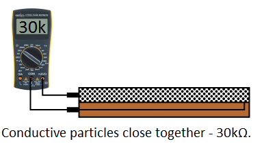
Orientation is up in running. Next thing we need are some flex sensors. The idea here is that the flex sensors will go on the back of the finger's of the glove, and as the finger bends, we can read by what amount. We achieve this using Flex Sensors, a variable resistor that increases resistance as the body bends. A chemical ink is embedded into the sensor. It's conductive atoms will space out further as the it bends, increasing resistance. 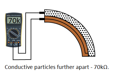
Voltage Dividers
We can turn a large voltage into a smaller one using voltage dividers. Two resistors in series will turn an input voltage into a fraction of the output. You'll see these everywhere. 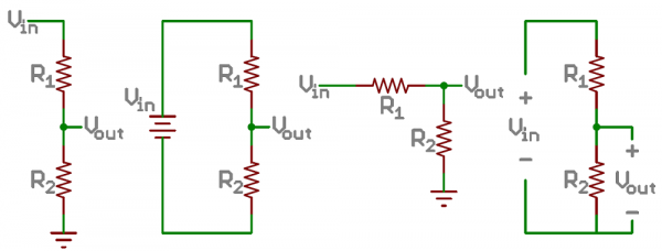 It follows this equation: $$V_\text{out} = V_{in} \times \frac{R_2}{R_1+R_2}$$ We need a voltage divider in our case, to read the change in resistance using the flex sensor and a fixed resistor.
On Gauntlet
Here's how it's looking on the breadboard: 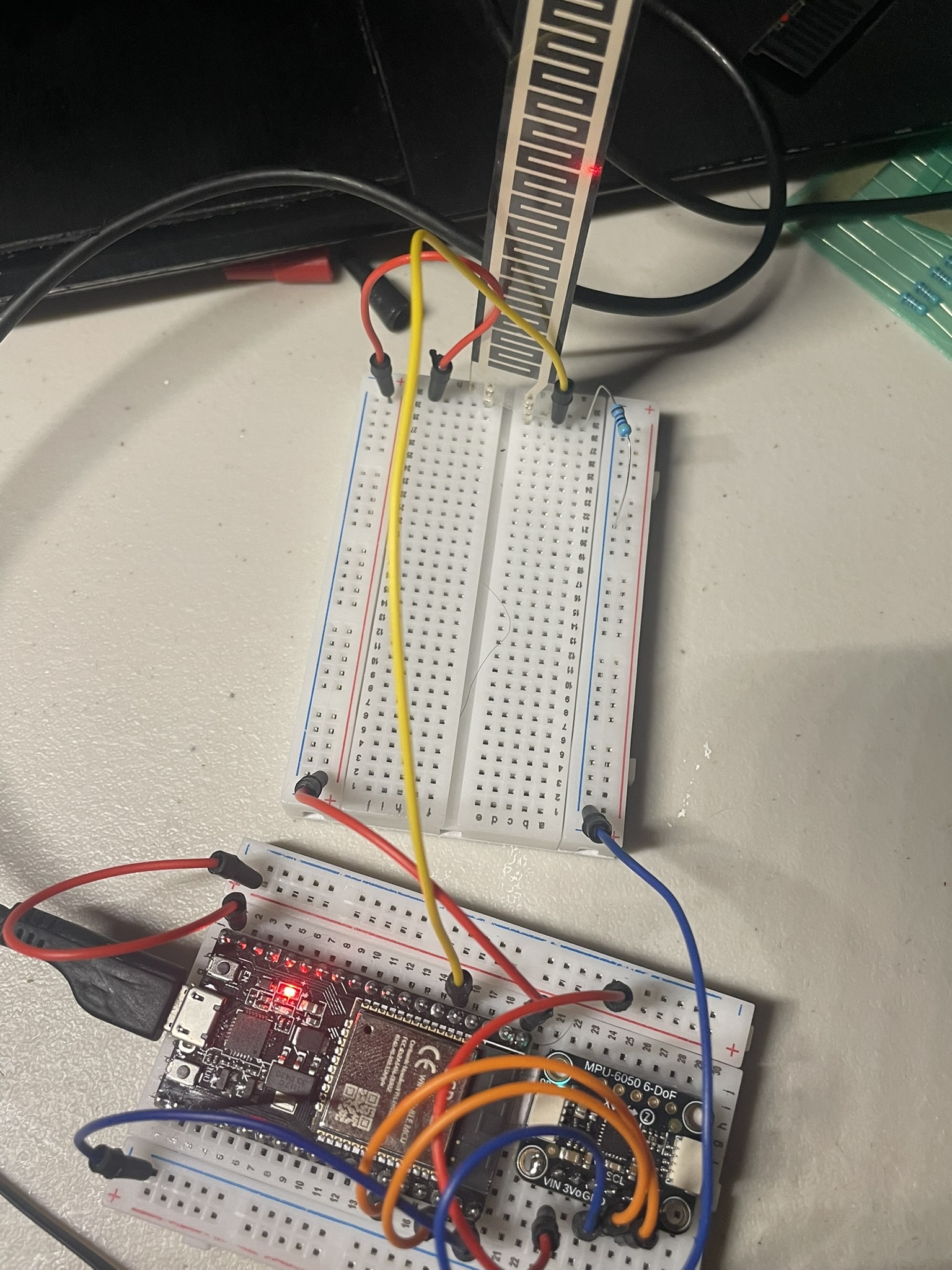 A simple set up. The yellow jumper will intercept the signal in the voltage divider: the flex sensor in series with the fixed resistor (47k). It's going into ADC1 (GPIO34). Apparently, some ADC pins act funky under wifi, so consult your datasheet for you specific MCU.
// ESP32 Arduino
// Wire: 3V3 -> Flex -> ADC node -> 47k -> GND, node to GPIO34 (ADC1)

const int PIN_FLEX = 34;     // ADC1 channel (safe with Wi-Fi)

void setup() {
  Serial.begin(115200);
  delay(200);
  Serial.println("Reading flex sensor");
}

void loop() {
  Serial.println(analogRead(PIN_FLEX));
  delay(10); // ~100 Hz
}
This simple script will output what ADC1 is reading. Here's what mine is looking like: https://youtube.com/shorts/0419PmKIG14?feature=share
Great. Let's turn it into some usable data. Here's a full script: gauntlet/basic/flex_test I've added some EMA smoothing like we discussed on the last part. There are some calibration methods on setup.
void setup() {
  Serial.begin(115200);
  delay(200);

  // ESP32 ADC configuration
  analogReadResolution(12);                 // 0..4095
  analogSetPinAttenuation(PIN_FLEX, ADC_11db); // up to ~3.3V range

  // Quick guided calibration
  Serial.println("Hold the finger STRAIGHT...");
  delay(1200);
  adcStraight = readAveragedADC(PIN_FLEX);
  Serial.printf("adcStraight = %d\n", adcStraight);

  Serial.println("Now BEND the finger to max range...");
  delay(1200);
  adcBent = readAveragedADC(PIN_FLEX);
  Serial.printf("adcBent = %d\n", adcBent);

  // Ensure order (handle wiring that inverts)
  if (adcBent < adcStraight) {
    int t = adcStraight; adcStraight = adcBent; adcBent = t;
  }

  ema = (float)readAveragedADC(PIN_FLEX);
}
readAveragedADC simply takes in multiple inputs from ADC in a few microseconds and creates an averaged value. We can grab a straight and bent value, eventually I'll add some more dynamic methods to fool-proof later on and update as the sensor grabs newer maxima and minima.
int readAveragedADC(int pin) {
  long sum = 0;
  for (int i = 0; i < SAMPLES; ++i) {
    sum += analogRead(pin);
    delayMicroseconds(500);
  }
  // Simple median filter could be used here instead of average for robustness
  return (int)(sum / SAMPLES);
}
Degrees doesn't seem too accurate, and I'll also improve on this. But for now, our output looks something like this:
...
ADC=3811  bend=20.2%  angle≈16.1°
ADC=3812  bend=34.1%  angle≈27.3°
ADC=3836  bend=45.5%  angle≈36.4°
ADC=3868  bend=55.1%  angle≈44.1°
ADC=3904  bend=63.2%  angle≈50.6°
ADC=3945  bend=70.3%  angle≈56.2°
ADC=3972  bend=76.3%  angle≈61.0°
...
It wouldn't make sense to start adding more flex sensors at this point. I need somewhere to put them, so I'll do some soldering and build out the glove next.